Did you know…
- that you can open a menu to display all of the sketch relations in the current sketch?

This is the place for shorter articles that still provide some real value.
Sometimes they are aimed at the starting user, sometimes at those with years of experience.
Parametric 3D CAD makes the life of the engineer so much better.
It doesn’t necessarily make it easier, nor does the first iteration of a design go much faster. But revisions will happen. And when they do, parametric designs will certainly be updated significantly quicker than 2D AutoCAD designs or drawings by hand.
But sometimes you just want to do something that was a piece of cake when drawn by hand. Adding a few milliliters of oil to the bill of materials (BOM) of a gearbox assembly is such a matter.
It can be done however. I’ll show you how to do it manually and by using the API.
Continue reading “Customizing the bill of materials quantity”
An updated version of this post can be found at the CAD Booster blog.
In my first years, suppliers frequently came back to me with questions and missing dimensions. One time I received the remark: “Why is there a radius dimension on the drawing when a diameter would be more useful? I can’t believe you let your software determine what you can or can’t do.”
I told him he had a point, but that I couldn’t change the dimension to a diameter. Turns out I was wrong.
Continue reading “Turning a radius dimension into a diameter”
Did you ever have to deal with a SolidWorks model so complex you couldn’t really locate the feature you were looking for? And did that situation occur time and time again?
Note: an updated version of this blog post can be found here.
Here is another quick tip for you. It’s a feature that you don’t easily find when you’re just fiddling with SolidWorks, it basically has to be pointed out to you by someone else (thanks Ryelle!).
I am very detail oriented when I am setting up 3D models. That is why the part/assembly at the top of my assembly tree is always the main component. It can for example be the frame of my machine, or the surroundings where the machine will be installed.
When this component is inserted, I immediately remove the fixed position property (right click > Float) because it looks like a lazy person just left it there. Then I add three mates: Front Plane to Front Plane, Top Plane to Top Plane and Right Plane to Right Plane. It is a chore to do this every time, but there is no other option. Or is there?
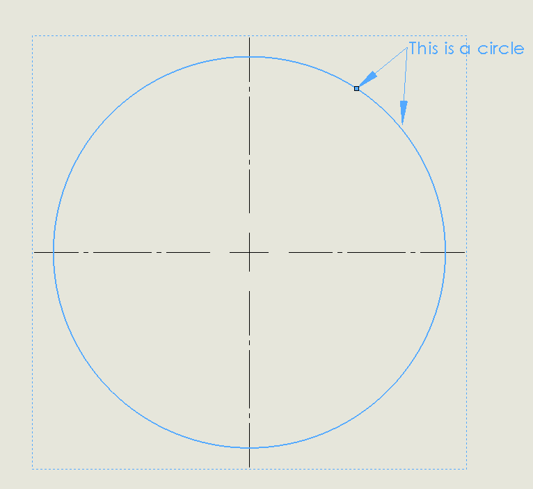
A few months ago I asked myself the question: how can I add multiple arrows (or leaders) to notes? Yesterday I received the same question from an experienced used, so I thought I’d write a quick tip about the subject.
It turns out to be easy. When you have an existing note, just click the point of the arrow of an existing annotation, hold the ctrl key and drag out another leader!