The SolidWorks sheet metal toolbox is a very powerful one to have.
The basics are child’s play, but there are lots of toys for the grown ups to play with as well.
I just read that you can create more than one body in a single sheet metal part. Here’s what I’ve learned so far.

Sheet metal intro
I truly hope that if you have ever designed a piece of sheet metal that had to be cut and bent, you’ve used the built-in sheet metal functionality.
We are in the prototyping and one-off machines business, so we use a lot of laser-cut sheet metal to build quickly and keep things affordable.
When I’m in doubt if some simple plate will require the sheet metal toolbox, I always use it. I even use it for flat metal parts because somebody in the future would like to add some tabs or flanges. Modeling the part as sheet metal will also enable you to place a flat pattern in a drawing.
Hidden powers
How often do you use the buttons in this toolbar beside the Base Flange/Tab and the Edge Flange?

Most of the items on this toolbar I rarely even use. But as it turns out, even the buttons that I do use have hidden possibilities.
Base Flange/Tab is called that way because, besides creating a base flange, it also lets you add tabs to existing parts. The Edge Flange will let you merge multiple sheet metal bodies.
There’s so much more to learn.
Multibody parts
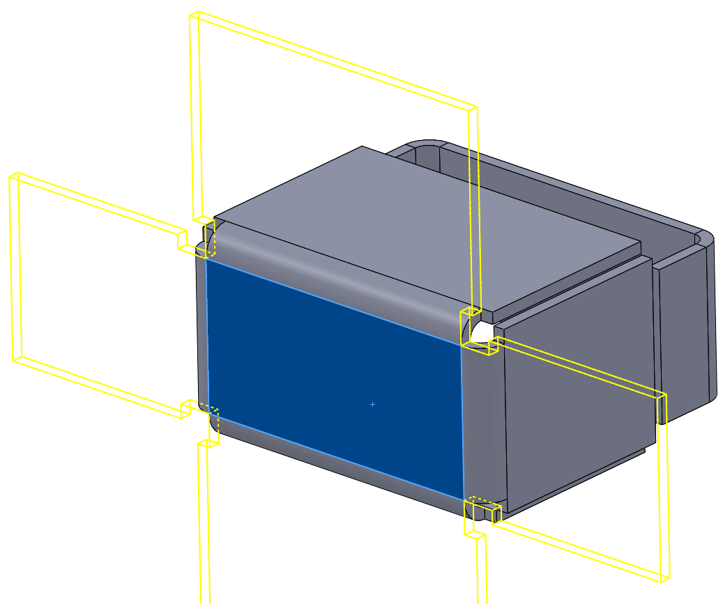
It turns out you can just create multiple base flanges in one part to get multiple bodies. I was quickly able to create the part shown above.
This video by CADVision will show you a few of the basics.
Especially the the part where he selects two edges to create a flange between them intrigues me. This result can be achieved by selecting two edges on different bodies, or by selecting “Up to edge and merge” at the Flange Length options after selecting the first edge.
I wasn’t able to reproduce this feature at first, but it turns out my two bodies were of different thicknesses. Of course they needs to be identical for this to work. You can merge only two bodies at a time.
The video below has a more in-depth look at the Up to Edge Flange
Random findings
Some things I’ve noticed:
- Most sheet metal features can only be added to a single body at a time.
- You can cut holes through multiple bodies with a single feature
How to flatten multibody parts
The default Flatten icon is not sufficient for getting an overview of multibody sheet metal parts. When pressed, it only shows the flat pattern of the first body.
The best way now is to right click the body that you need to flatten and select Flatten. As shown in the video, you can also right click the part > Toggle Flat Display. Left clicking outside of the part will close this view.
As usual, there is also a derived configuration with the flat pattern. Only now, there’s one config for every body.

Drawings
When you start creating a drawing and you want to add flat pattern views of all bodies, this menu changes slightly.
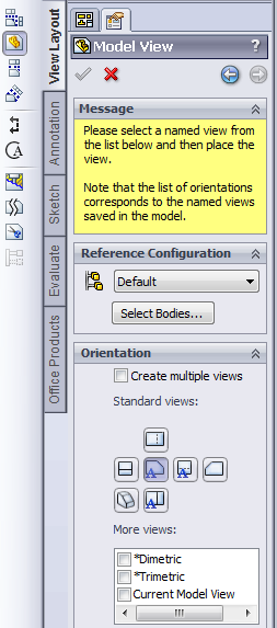
There is no flat pattern option here, because all bodies are included in this view. Clicking Select Bodies will take you back to the 3D model to select one or more bodies. When you select a single body, you will then be able to add a flat pattern view.
Do this for every body and you’ll get something that starts to look like a drawing.

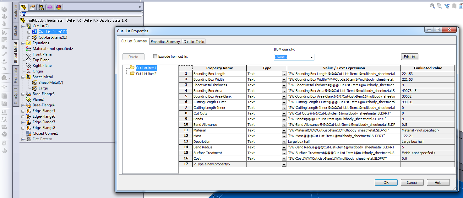
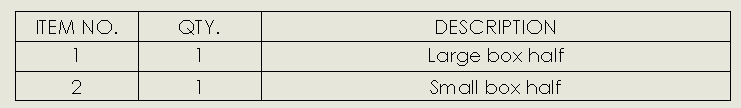
The standard cut list isn’t very useful yet. My least imaginative colleagues (that name every part “Plate”) could come up with better descriptions than that. You can edit the description when you right click a body in the Cut list feature in the tree.
This already looks way better. Maybe I should give them a number though.
If you want to use this description in a note, the variable that you need is $PRPWLD:”Cut List Name” according to this forum topic.
Exporting
Some companies use the built-in functionality of SolidWorks to create DXF files for the laser cutter. You can access this feature by choosing Save As > DXF.
This function needs some extra attention when it’s used with multibody sheet metal parts:
- Select the body that you want to export
- Choose Save as > DXF
- Pick a filename and click Save
- Set the Export option to Sheet Metal
- Select the bend lines and other entities that you want to include
- Click the green checkmark
- Check the preview
- Click save
When I try to export the DXF without pre-selecting a body (either as a single file or as multiple files), the result is these overlapping shapes in my DXF. This might be workable, but it’ll probably go wrong somewhere along the supply chain.

Splitting parts
Suppose you would like to split a multibody sheet metal part into separate files, how would you do this? I’ve found one proper discussion at the SolidWorks forum and the best that they could come up with is:
- Suppress all but one body
- Save the body as a part
- Open the new part
- Convert it back to sheet metal (check the K-factor)
It isn’t pretty or quick, but it’s doable if you really want to have separate files.
Preliminary score
In the short time that I know that you can create multibody sheet metal parts, I’ve learned a lot already. Here are some of the pros and cons of using them. I must note that I haven’t used these features in production though.
Advantages
- You can create an intricate sheet metal model with only one part
- The DXF export still works properly for single bodies, although with an extra step
- You can merge two bodies that used to be modeled as individual bodies
- You can disconnect bodies without having to create new parts
Disadvantages
- Most companies are not set up for this way of handling sheet metal
- There’s no proper way to separate the single file into multiple part files
- You need to add a flat pattern of each body to a drawing
- The standard flatten feature works only on the first body
Conclusion
I find this feature a bit tricky. It has so much potential because you can create complex parts within a single part file. This will also mean fewer mates in the assemblies.
You might really mess up your company’s workflow though if you just decide to start using it. I would only advice you to do that if there are only a few employees and you have control over the entire workflow.
Did I miss any major feature for multibody sheet metal parts? Do you use them or do you advise me not to use it? Please let me know in the comments.