Note: An updated version of this post can be found here.
Once you have learned how to use weldments, you will wonder how you have done without them for so long.
You can quickly sketch, build up and redesign complex frames made from standard pipes and beams. A single drawing will usually suffice.
But sometimes, you just want to create a detailed drawing for one or more weldment sections. Here’s how.
Weldments
I couldn’t even find references to weldments being introduced in SolidWorks, so this functionality seems to be in there for long time. The blogs that wrote about the introduction have probably vanished already.
(I did find this PDF file on the new features of SolidWorks 2000 though, they include polygons, crop views and stacked balloons. No mention of weldments yet)
Some day in the future I will write a massive article on the major features of the weldments toolbox. Today is just not that day. If you can’t wait, here’s a video by GoEngineer on the weldment basics.
Part-by-part drawings
Suppose you have a few complex members in your design. Or, like they did at my last assignment, make some of the sections in-house while outsourcing others.
I just designed a frame for a side table to show you how it works.

The standard way of creating a drawing for a weldment will result in something like this:

Two options
There are basically two possible ways of creating drawings for each part:
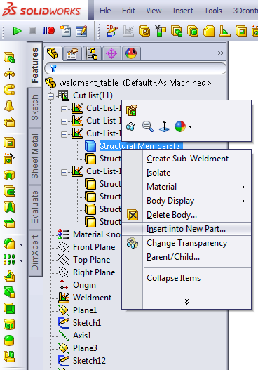
- Right click a cut list item and select Insert into New Part
- Create a Relative View for each part or for a set of parts
The first method will create a new part that is linked to the original weldment, so it will get updated when the weldment sketches are updated. This method creates too many part files for my taste, so we’ll go with door number two.
A relative view lets you create a new view where you can choose the orientation of the planes. The main reason we use it here, is that you can also select which bodies to show.
Adding a Relative View
The fastest way to create such a view is by adding the Relative View button to the taskbar first by going to the Customize window and dragging the icon from the drawing category it into a toolbar.
Now select an existing view, click the Relative View button and SolidWorks will take you to the 3D model. You can select the option Selected Bodies, choose a body and then select two faces to determine the orientation.

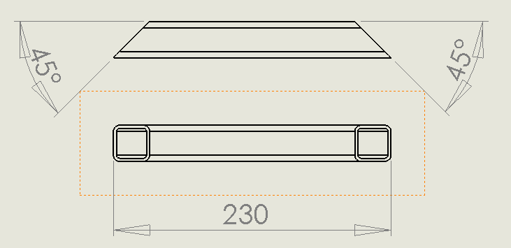
When you accept the options, you will return to the drawing. The front view of the body you selected will now be inserted. With the options selected above, the result will be like the image below.
Note: I already added a projected view above to be able to add some crucial dimensions.
Once you’ve done this for all of the items you deem necessary, it’s time to get something built!
Creating separate views for all cut list items might not be the greatest task in the world, but it will surely clarify the drawings of complex weldment items. And who doesn’t like their parts to be correct the first time?
MOAR!
Want to learn more? There is a one day official training that your VAR should be able to help you with. You can even get certified by passing the Certified SOLIDWORKS Professional Advanced Weldments (CSWPA-WD) exam. Good luck!